- Maxwell wheel: Diameter of wheel: 130 mm approx, Mass of wheel: 972g approx. Suspending rod: 370 mm x 12 mm dia, Material: Aluminum
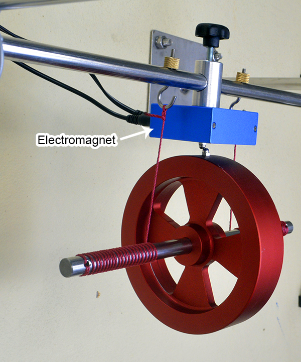
- Electromagnet: 5V-DC, switch ON/OFF to protect coil.
- Power supply: 5V DC
- Stainless steel rod dia. 10mm: length 1000mm with red lines 5cm apart
- Stainless steel rod dia. 12mm, length 400mm, with two adjusting hooks
- Right angle clamps (3 pcs)
- Thread cord (1 coil)
- Wall holder (2 pcs)
- Tape ruller 100cm
- Investigate the conservation of mechanical energy
- Investigate the transformation of potential energy into translational and rotational energy
- Determination moment of inertia of the Maxwell wheel
Click link to see price: https://en.aelab.com.vn/maxwell-wheel


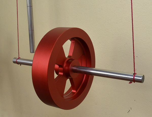
Theory:
Total mechanical energy of Maxwell’s wheel includes potential energy Epot, and kinetic energy Ekin. In which, kinetic energy Ekin includes rotation kinetic energy Erot ( rotation) and Etrans (translation).


I: Moment of inertia of Maxwell wheel
h: Height of Maxwell wheel rod
g: Gravitational acceleration.
m: Mass of Maxwell wheel
v: Translation velocity of suspend rod
ω: angular velocity
in the initial state, the wheel is stationary (v = 0 and ω = 0). When the Maxwell wheel falls, we have the following formula:

With the radius of the wheel axis r, so velocity v:
v = ω.r (4)
Then, the inertia of the Maxwell wheel:

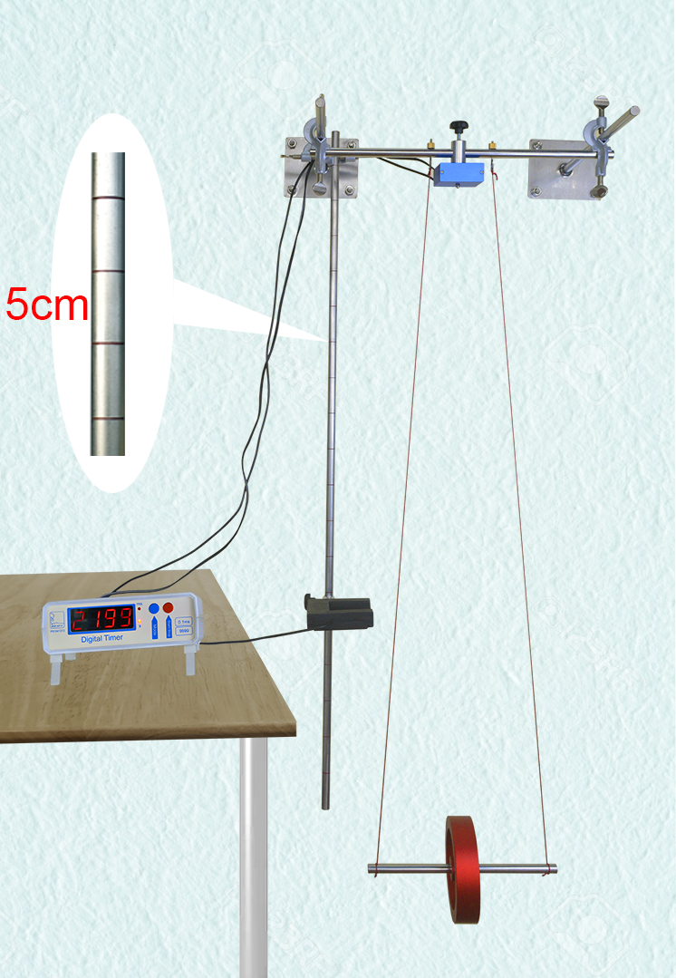
- Maxwell wheel experiment is set up according to Figure below:
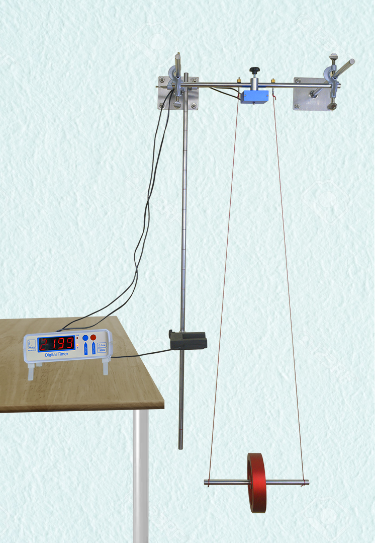
Maxwell wheel experiment
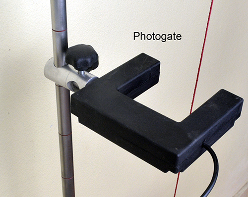
- Attach the photogate so that the axle of the maxwell wheel scans the IR eye. Then plug to port 1 of timer
- Plug electromagnet to port 0 of timer
- Plug power supply 5VDC to electromagnet.
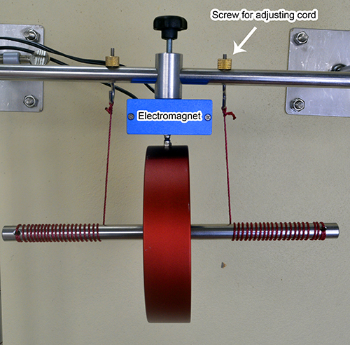
- Tie the cord to the maxwell wheel shaft and adjust the length of the cord so that when wound up to the highest position, the pin of the electromagnet contacts the pin on the wheel (figure below):


- Length of cord: <1m.
- Release the maxwell wheel several times to stabilize the cord length, and fine adjusting by screws above.
- Positioning the photogate at position 1 with 5cm
- Adjust the photogate so that the wheel shaft does not collide with the photogate (Note: after release the wheel, use your hands to touch the cord to reduce vibrations)
- Turn ON the timer and select Mode 3
- Switch ON the electromagnet
- Wound the cord to attach maxwell wheel to magnet.
- Attach the photogate to the first position 5cm from lowest edge of the wheel axis
- Press Start/Stop to release maxwell wheel. After pass the photogate, press Start/Stop again to display time: time from magnet to photogate (t) and the time the wheel shaft sweeps through the photogate (Δt)
- Each position we do 3 times, and remove any suspicious data. Then take the average value.
- Lower photogate to position 2 (10cm), do again, and write to data table below:
Calculate the velocity v according to:

d = 12mm: diameter of wheel axis
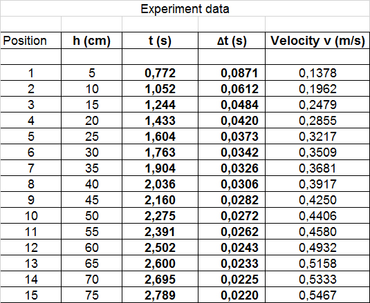
Graphing h ~ t and v ~ t below:

Adding trendline, it is obvious, that the values for the velocity follows a linear function, while the values for the height follows a parabolic function.
From equation (5) we get a value for the inertia I for each measurement below:
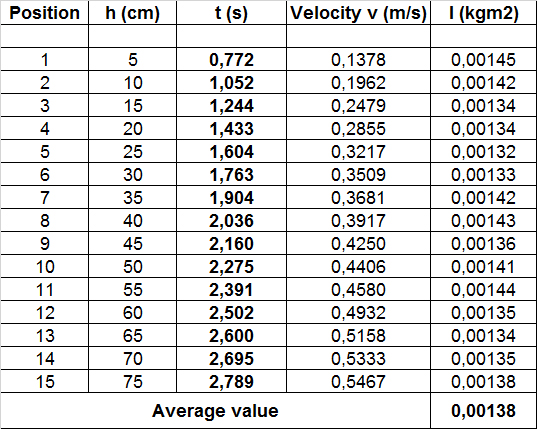

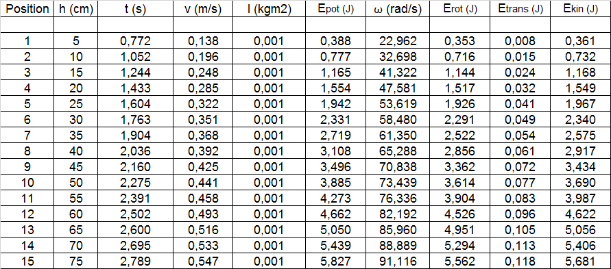
From equation (4), we get angular velocity ω
Then we get Epot, Erot and Etrans.
Graphing Energy ~ t below:
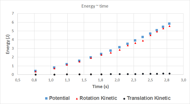
Since the values for the translational energy are quite small, we can conclude that most of the Kinetic energy is rotational Kinetic energy.
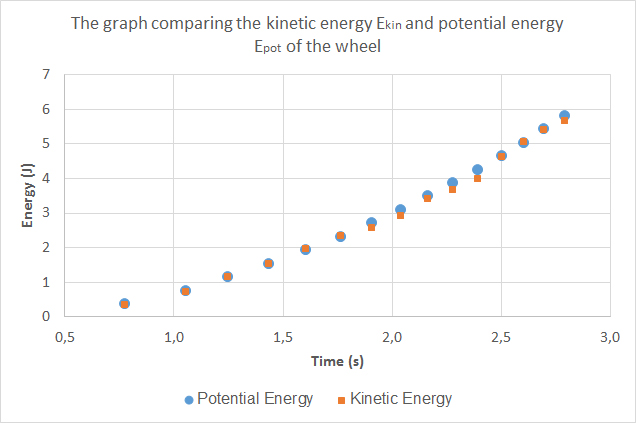
Kinetic energy Ekin as a sum of the rotational Erot and translational energy Etrans (see on data table above)

Compare kinetic energy and potential energy based on the graph below, we can confirm the conservation of energy when transform from potential to kinetic energy in the maxwell wheel experiment.
